
 All RADAR and EW systems need extensive test and evaluation (T&E) before being deployed and often require periodic re-evaluation during their system lifetimes. Although field trials (ground, flight or naval operations) are the most accurate predictor of operational effectiveness, such exercises are too expensive to rely on exclusively for design feedback. Furthermore, defects uncovered during the field trial stage usually results in major program delays and cost overruns. To reduce this risk, the defense industry invariably relies on simulation in a laboratory setting to save development costs and to identify problems early.
Simulating the electromagnetic environment that modern weapon systems will experience when deployed is a challenging problem. Simulators must generate hundreds if not thousands of signals simultaneously in order to replicate the dense environment like that encountered in a modern battlespace. It’s also necessary that many of those signals change dynamically with time to simulate movement. These dynamic signals are injected into the system under test (SUT) for the purpose of predicting its operational performance when placed in service.
To limit the amount of hardware needed, modern simulators are constructed using signal generators that can precisely control their carrier phase, allowing one signal generator to simulate multiple emitters. Consequently, the phase stability of all the generators in the system relative to each other over a long period of time, becomes an important figure of merit. This paper discusses the relative phase stability between multiple Advanced Signal Generators within the Giga-tronics AXIe platform.
The Giga-tronics Advanced Signal Generator (GT-ASG18A) was designed specifically for use in modern simulation systems. Its separate reference module permits each signal generator within a chassis to share a common clock. This improves the achievable channel-to-channel phase stability over traditional designs that can only phase lock the individual signal generator references together. The main elements of the Giga-tronics Advanced Signal Generation Platform are shown in figure 1.0 below.
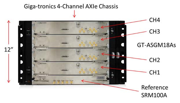
Figure 1.0
The Giga-tronics system reference module (GT-SRM100A) contains a provision to accept an external clock thereby allowing one reference to drive multiple chassis. The configuration of one SRM driving multiple chassis is shown in figure 2.0 below.
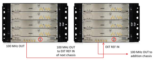
Figure 2.0
The 100 MHz crystal oscillator in the SRM labeled #1 replaces the 100 MHz crystal oscillator in the reference labeled #2 and thus becomes the true single reference for all eight ASGs in both chassis. This daisy chaining of references can be extended without limit.
A method of measuring the phase drift between any two ASG channels was devised using the concept of cancellation as illustrated in figure 3.0 below. While other methods of measuring drift were considered, such as tracking zero-crossings on a multi-channel oscilloscope, it’s difficult to obtain a scope with enough stability (i.e. better than the Giga-tronics ASGs) in order to make an accurate measurement.
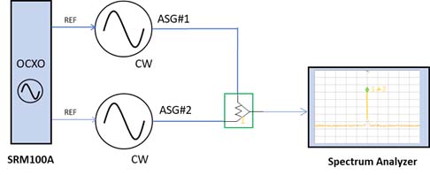
Figure 3.0
The method of cancellation doesn’t depend upon the stability of external test equipment and thus becomes an inexpensive way to make an accurate measurement of phase drift between two ASGs tuned to the identical frequency. For example, any two given ASG channels can be represented by signals A & B in figure 4.0 below. In the ideal case, summing the two RF outputs and appropriately adjusting the phase and amplitude of one relative to the other, will result in the summed RF waveform being driven to zero. Complete cancellation occurs when the relative phase is 180 degrees and the amplitudes of the two waveforms are precisely matched. One drawback of this method is that the cancellation is dependent upon the ability to exactly match the amplitudes of the two channels and setting the relative phases to 180o. Figure 4.0 also illustrates what happens when the relative amplitudes are not precisely matched or the relative phase between the two channels is not precisely 180 degrees.
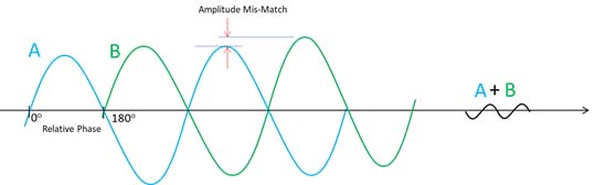
Figure 4.0
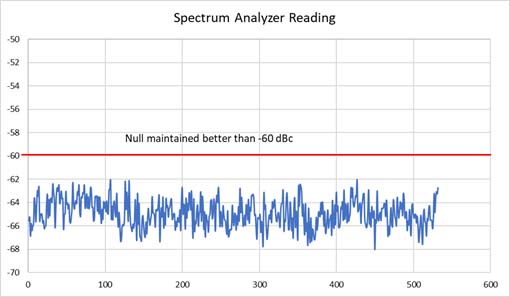
However, an advantage of this method is that a simple spectrum analyzer or power meter can be used to measure the degree of cancellation. With the amplitudes matched (resolution available < 0.01dB) and the phase adjusted (resolution available = 0.1o) for minimum signal, the degree of cancellation achievable is better than 60 dBc as shown in figure 5.0 below.
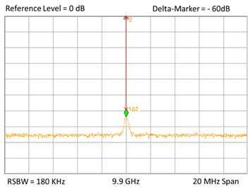
Figure 5.0
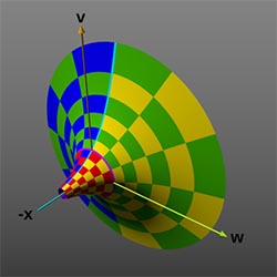
An additional advantage is that the degree of cancellation is quite sensitive to small changes in either amplitude or phase around the vicinity of complete cancellation, particularly when measured in dB. The mathematical 3-Dimensional graphic on the first page of this document is an attempt to illustrate the high sensitivity of the log function with two parameters (amplitude and phase in our case) around the vicinity of a null. A 2-Dimensional log plot showing the sensitivity of the cancellation to phase changes around the vicinity of complete cancellation for different levels of amplitude matching is illustrated below in figure 6.0. The chart demonstrates that even with only a moderate degree of amplitude matching, a half degree of phase change will produce a 10 dB change in the magnitude of the summed waveform.
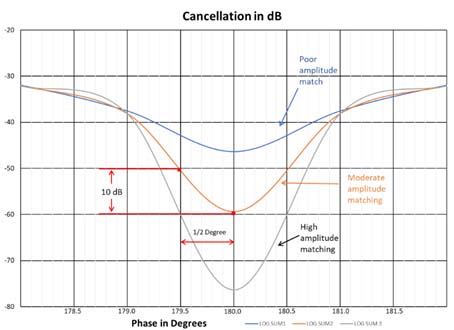
Figure 6.0
The stability of the Giga-tronics Advanced Signal Generators can be demonstrated by monitoring the resulting waveform of the summed channels on a spectrum analyzer and adjusting their relative amplitude and phase to maintain a minimum signal. If the two individual waveforms are stable in amplitude and phase relative to one another, then the summed waveform will remain at its minimum. Any drift in either amplitude and phase will cause the cancellation to become less complete and the resulting summed waveform will grow in magnitude, which can be easily measured on a spectrum analyzer. The recording of stability was accomplished by continuously adjusting the amplitude and phase of one channel relative to the other to maintain the summed waveform at its minimum and then saving the phase value required to achieve that minimum. This approach was automated through software running on a PC and is illustrated in figure 7.0 below.
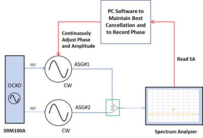
Figure 7.0
During the process of refining the measurement approach, it became obvious that temperature variations had a large influence on the phase stability of each channel. The measurement setup was in a laboratory setting within the Company’s main factory without any special accommodation for controlling the temperature other than from the building’s HVAC system.
Furthermore, it was determined that the method of adjusting the relative amplitude between the channels also introduced a small phase shift of its own which created an error in the parameter of interest – i.e. the phase shift caused by making amplitude corrections required compensating phase adjustments to keep the summed waveform at its minimum. Two steps were taken to alleviate these issues as follows:
The measurement setup is shown below in the series of photos 1 through 3.
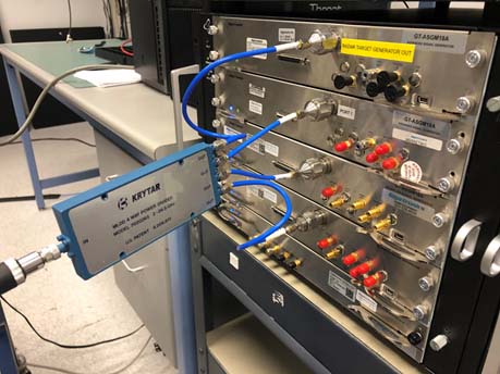
Photo 1 showing the four channels of ASGs summed using a power combiner
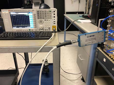
Photo 2 showing the output of the power combiner connected to a spectrum analyzer
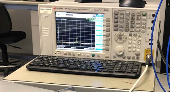
Photo 3 showing a closeup of the spectrum analyzer measuring the cancelled signal
The measurement method described in this paper was found to be successful as demonstrated by the degree to which cancellation could be maintained over the 9-hour period as shown in figure 8.0 below. The summed waveform was maintained at a minimum value better than -60 dBc.
Time in Minutes
Figure 8.0
Although both the relative channel-to-channel amplitude and phase were adjusted continuously to maintain the summed waveform at its minimum, only the phase setting required to maintain the minimum was plotted. The ambient temperature was also recorded at the same time. Readings were collected every 2 minutes for approximately 9 hours and written to a csv file in Microsoft Excel.
Only two channels were summed at any given time. No attempt was made to null the summation of all four channels simultaneously. One channel was designated as the “reference channel” and received continuous changes to its amplitude and phase to maintain the null with the “selected” channel. The selected channel was held static in its amplitude and phase setting following the initial settings of its amplitude and phase. The result for selected channel #2 relative to the reference channel #1 is shown in Figure 9.0 below along with relative change in the ambient temperature that occurred over the measurement interval.
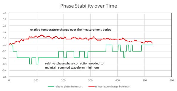
Figure 9.0
From analysis of data from all four channels, it appears that for every 1 degree Celsius of temperature change, the relative phase between two ASG channels operating at 9.9 GHz consistently moved 2o or 0.035 radians. It was therefore possible to correct the measured phase stability for variations in temperature. Temperature corrected plots showing the results obtained for three channels relative to the reference channel are shown in figure 10.0 below.
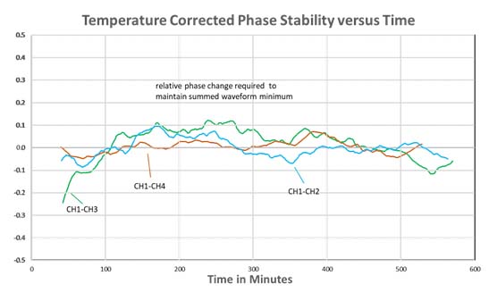
Figure 10.0
One of the original goals of the Giga-tronics AXIe Advanced Signal Generator platform was to address the need for multi-channel phase coherent signal generators within the defense industry simulation market. The results presented in this paper demonstrate that the architecture of the Giga-tronics ASG platform with its separate shared reference and its ability to daisy chain multiple chassis together can deliver multiple independent microwave channels with excellent phase stability over long periods of time without the need for additional hardware to synchronize channels. The AXIe modular platform helps deliver this benefit in a much smaller form factor than racking and stacking multiple benchtop sources.
One should bear in mind that temperature changes can induce phase shifts throughout a measurement system and must be considered carefully when attempting to isolate the contribution of any one element within that system. The plot in figure 9.0 shows how much phase shift can occur between channels even with only slight changes in ambient temperature.
When phase stability between channels is critical, some form of temperature stabilization, such as keeping the generators in an air conditioned rack or in an oven at a constant temperature, will likely be necessary. The plots shown in figure 10.0 above indicate that the ASG channels can be kept to within a few tenths of degrees of each other when the effects of temperature are addressed.